
THE SOLUTION FOR ISTVAN´S PROBLEM
18.07.2018 – 18:50 H
Just heard ISTVAN´S latest podcast.
The Situation is clearer now!
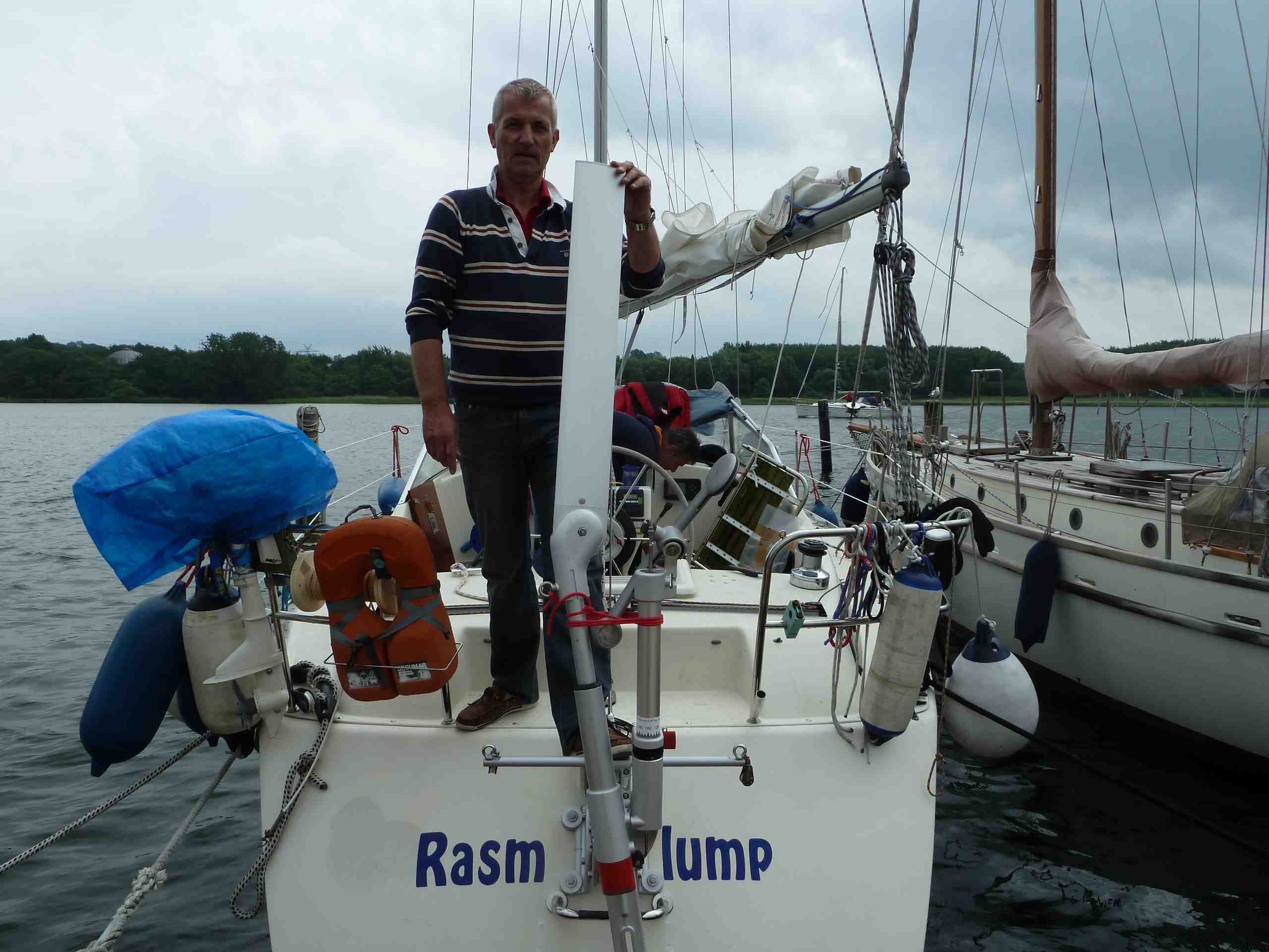
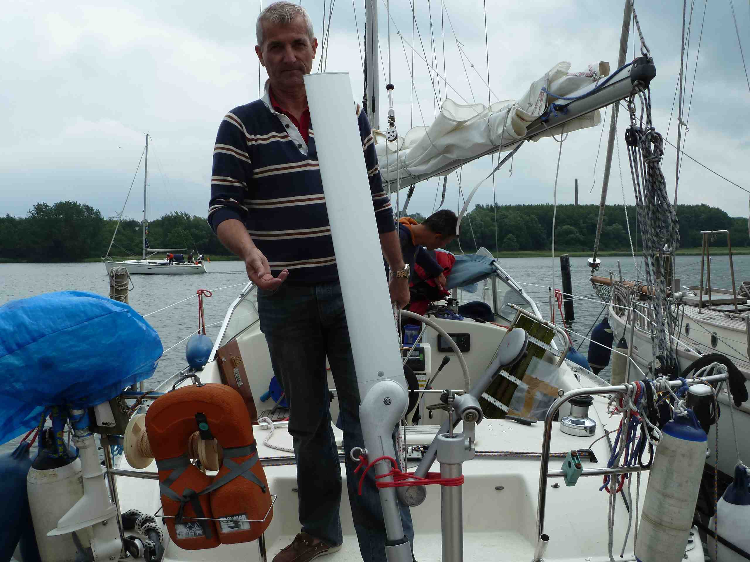
Whitlock Cobra direct drive wheel steering has a max number of turns from lock to lock of less than ONE. Istvan has confirmed that. He has explained the reason for choosing this type of steering: he wanted to get rid of cable transfer underneath cockpit and lazarette to achieve more stowage for the GGR challenge. Obviously he admitted his choice as to be a wrong decision.
Very certainly we now having detailed information to proceed giving specific advice to improve the problems with his Windpilot.
ABOUT TYPES OF WHEELSTEERING
standard cruising wheel steering types ( wheel diameter around 65 cm ) with max number of turns between end stops of around 2,4 turns
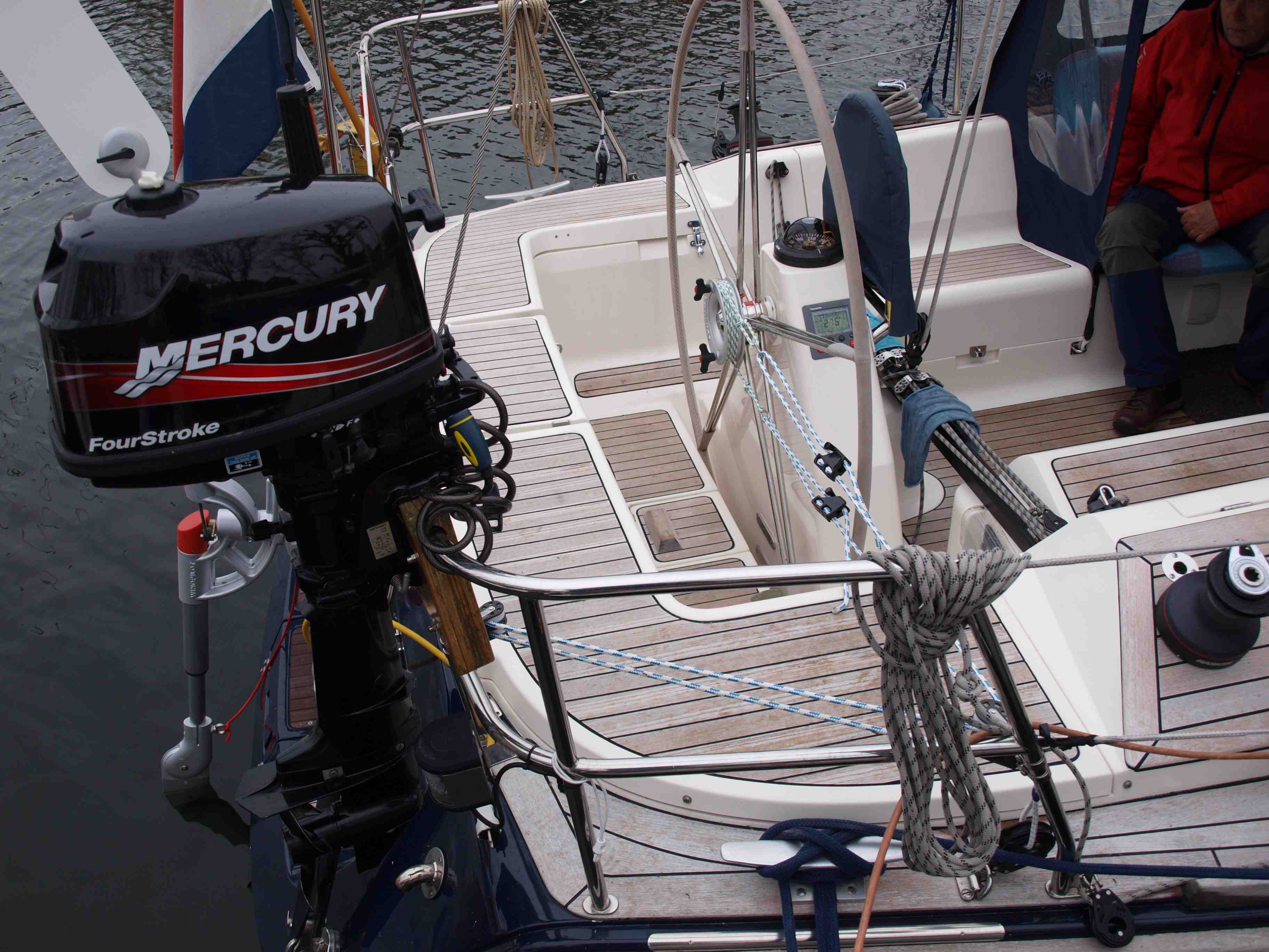
direct transfer ratio for performance boats ( wheel diameter around 100 cm ) and max number of turns about ONE total turn … or even less ( ISTVAN´S TYPE )
ISTVAN´S PROBLEM IS WRONG TRANSMISSION RATIO
Due to poor synchronisation between Windpilot and wheel steering. His Windpilot is generating too much of line pull rather enough power. Wider yawing will be the inavoidable consequence, i.e. Oversteering must happen. Its like driving a car uphill in forth gear = will hardly work.
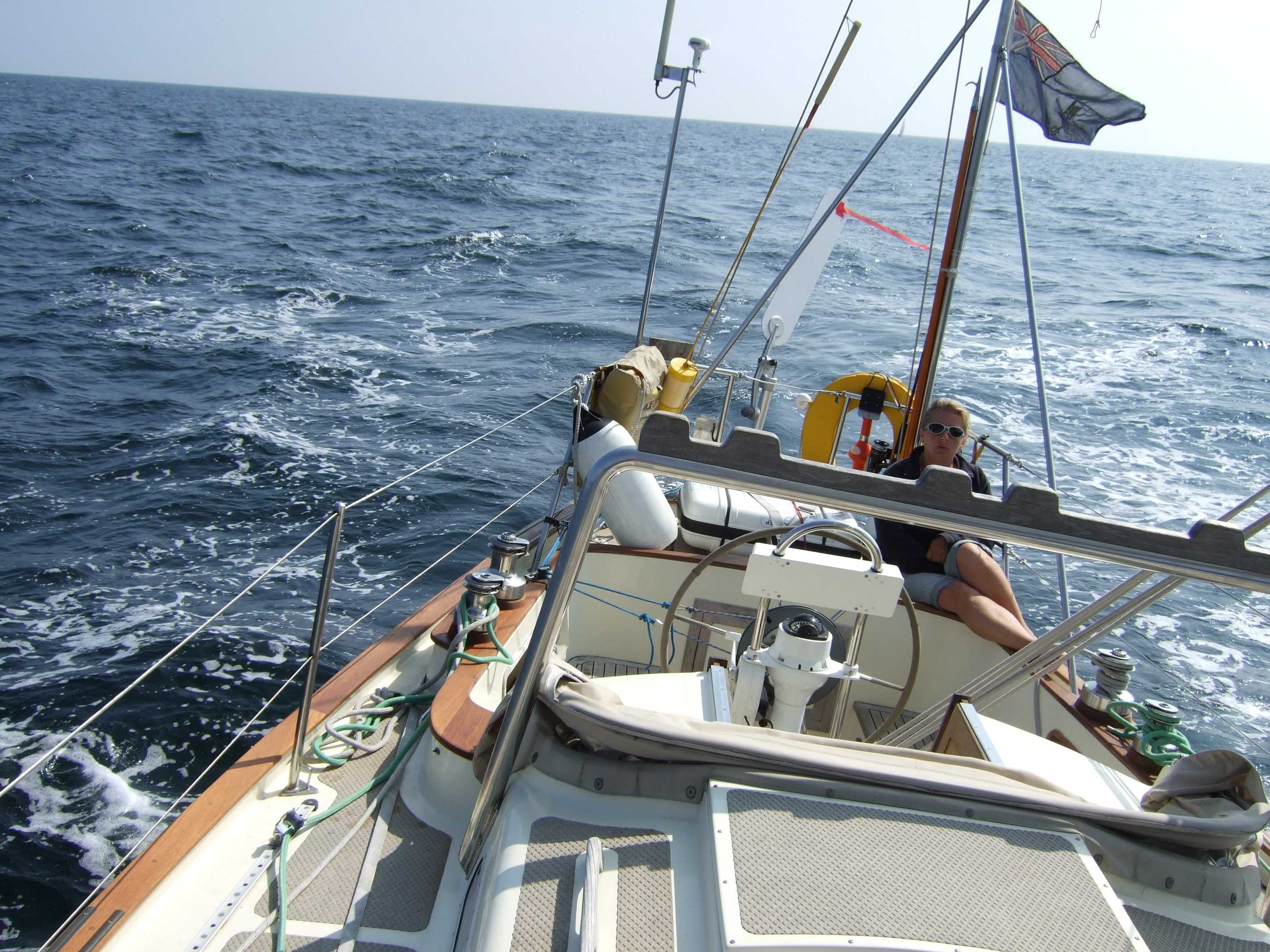
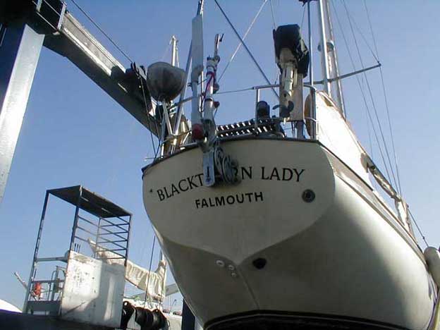
TRADEWIND 35 CHARACTERISTIC
Unless TRADEWINDS using tiller steering, they normally use wheel steering for cruising boats with cable transfer and max number of turns between end locks of about 2,4 turns. While this will be fine with any average pendulum wind vane steering system like Monitor or Aries and of course the Windpilot Pacific, it will hardly comply ( work ) with the needs / request of a direct transferring Whitlock Cobra steering system.
Istvan´s Windpilot will need MORE POWER and LESS WAY at the same time to cope with his wheel steering.
MAX LINE PULL
PENDULUM SYSTEMS CHARACTERISTICS – TRADITIONAL DESIGN CONTRA IMPROVED DESIGN
Instead of the traditional ARIES and MONITOR with a fixed line transfer ratio i.e. unadjustable line pulling capacity, the Windpilot Pacific design offers stepless adjustability at the pendulum carriage to cope with both, direct and more indirectly operating wheel steering type due to a longhole and stepless adjustable power transfer.
– upper third = average cruising vessel with wheel steering of 2,4 turns
– lower end = faster boats with direct transferring wheel steering of about 100 cm or even more
ISTVAN´S WAY TO SOLVE HIS PROBLEM
Istvan will have to play on the piano of adjustable line transfer ratio to improve the performance of his vessel.
THE MANUAL EXPLAINS HOW TO PROCEED
Chapter 1.6.8.2.
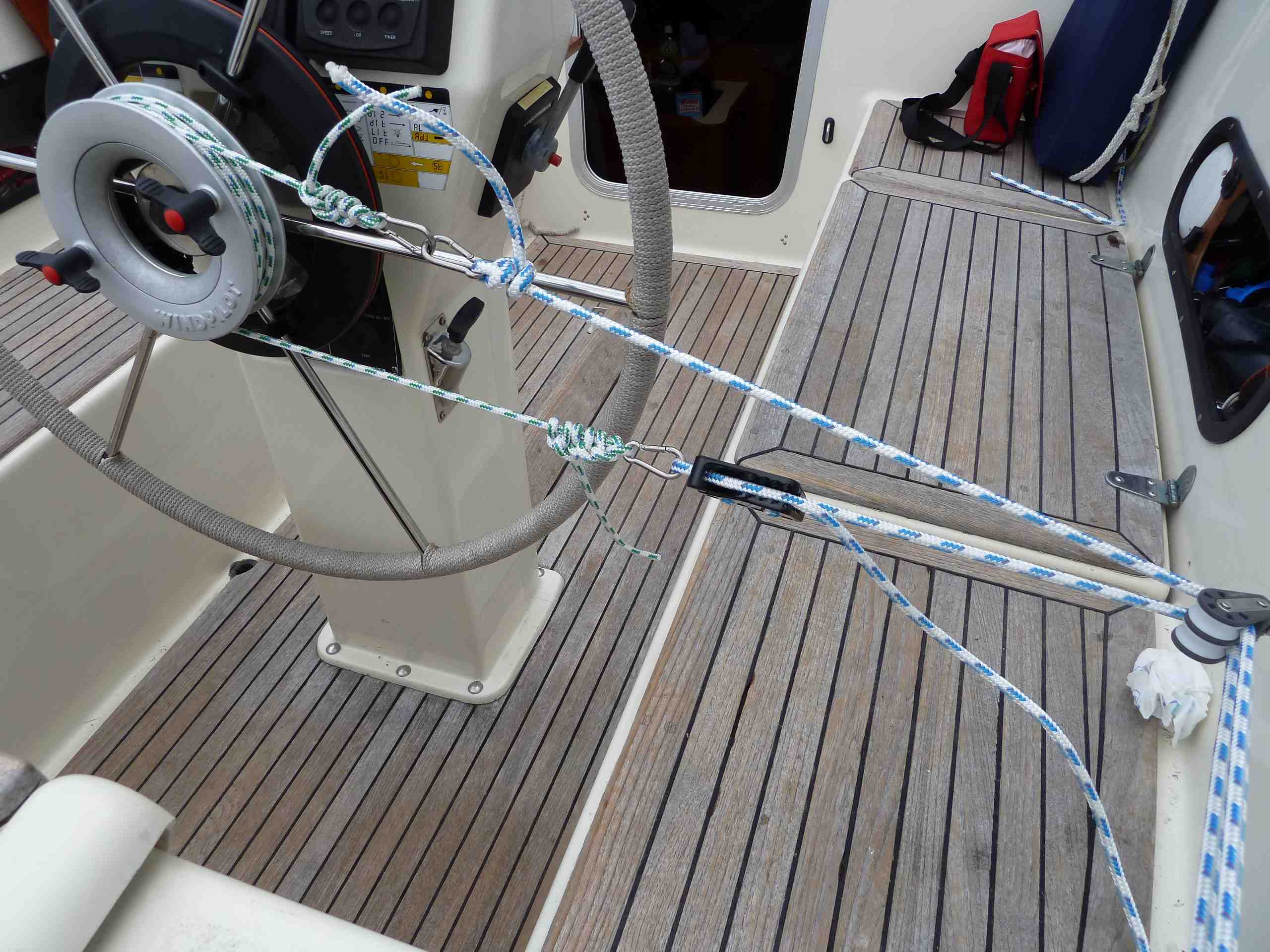
2.2.8 IS THE VARIABLE FORCE TRANSMISSION SET CORRECTLY?
With the boat making good speed, manually turn the windvane all the way to one side and hold it there:
If the pendulum rudder moves approx. 25 degrees to one side, the force transmission is set correctly.
If the pendulum rudder moves significantly less than 25 degrees, slide ring 345 a little further down the pendulum arm (less travel but more force).
If you have tiller steering, you could alternatively move the tiller fitting forward (never move the fitting aft).
2.2.8.1 DETERMINING THE IDEAL SETTINGS
The pendulum arm should always be able to make use of its full 25 degrees of travel to each side. This can be adjusted by moving the transmission point (ring 345).
TIP: leave the ring in the centre of the slot until you have tested everything properly under sail.
If the pendulum arm reaches 25 degrees off-centre too quickly and easily, move ring 345 up the slot (longer lever).
Keep testing the settings and moving the ring up until the lateral travel of the pendulum arm begins to be limited to less than 25 degrees.
Now gradually move the ring 345 back down the slot, testing the different settings as you go, until the pendulum arm is just able to reach the full 25 degrees of travel.
CAUTION: larger, heavier boats may need to reach a relatively high boat speed to move the pendulum arm through the full 25 degrees.
The force generated by the servo system is always dependent on leverage, rudder area and speed. These factors are the product of physical laws, the consequences of which are inescapable!
5.2 SYSTEM PERFORMANCE IS NOT SATISFACTORY
Is the pendulum rudder positioned correctly? See 1.7 The Pendulum Rudder.
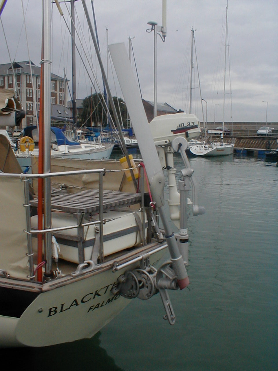
5.2.1 POSITION OF PENDULUM RUDDER BLADE
If the pendulum rudder blade is too far aft, the balance proportion will be too small and the system will only be able to steer at relatively low speeds. No effective steering impulse will be generated at higher speeds.
If the pendulum rudder blade is too far forward, the ✔ balance proportion will be too large. The pendulum rudder will be moving the windvane instead of the other way around, leaving the system completely
unable to steer.
Lower the pendulum arm into the water. If it immediately starts swinging around and seems unable to settle on centre, the pendulum rudder is too far forward.
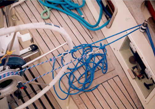
ISTVAN HAS TWO PROBLEMS TO SOLVE
1. change adjustment of stainless steel ringnut # 345 to lower end of slot in pendulum carriage part #330
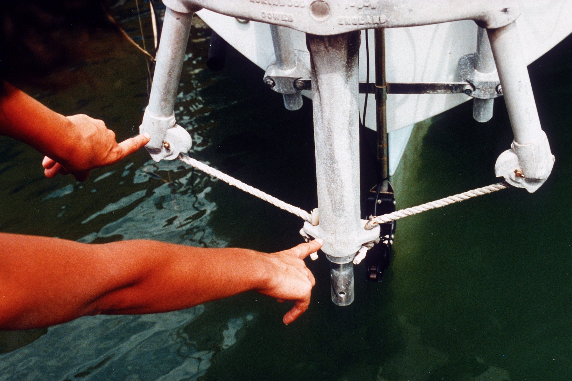
2. change positioning of servo rudder blade into EXACT alignment of the servo rudder shaft, which sticks out to the aft of 10 degree.
PERFECT POSITION
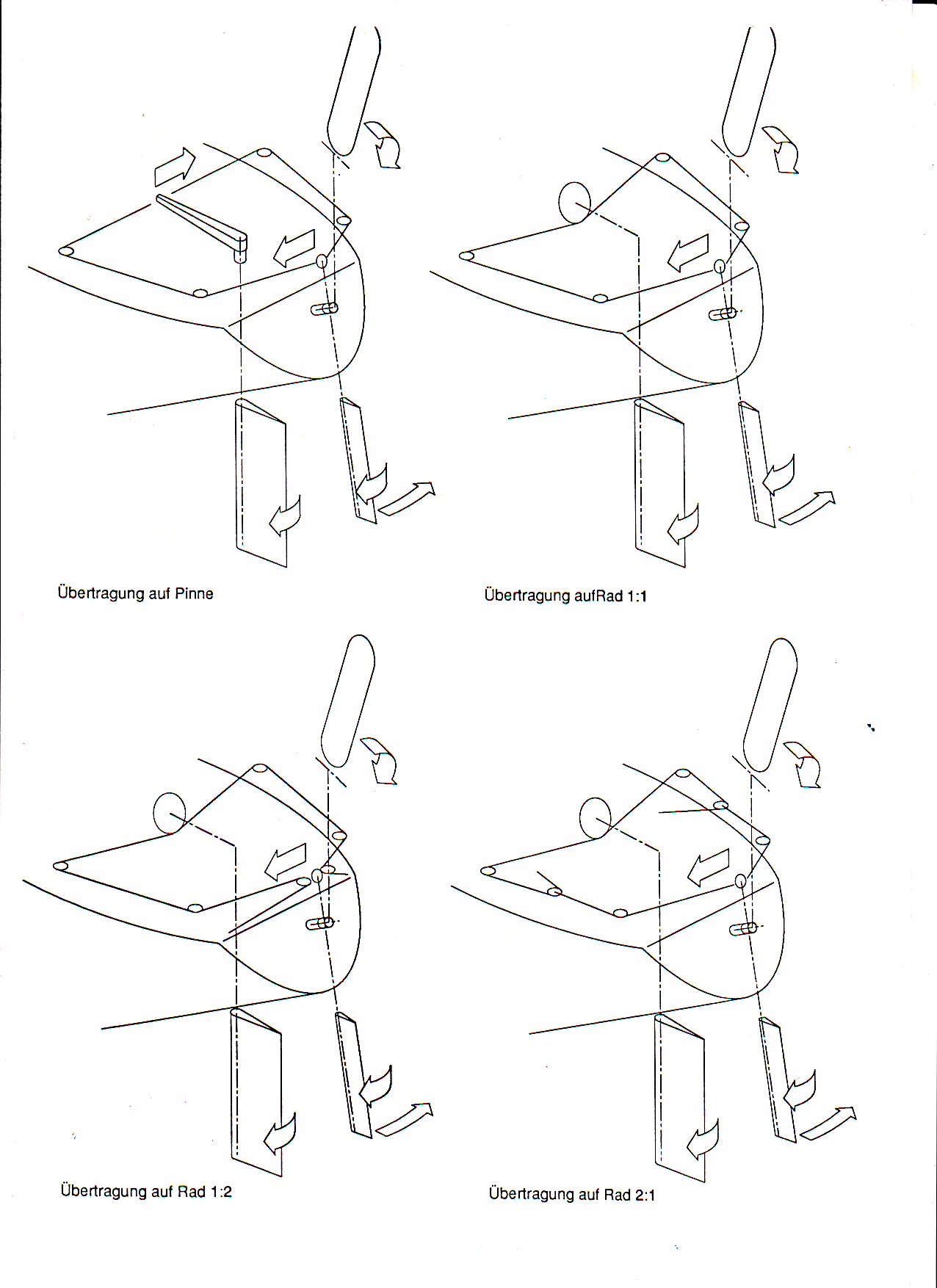
In case the reduction of power will not be enough, i.e. He might even need SMALLER turns of the wheel to prevent oversteering, here is the way to go:
Compare encl. drawing TRANSFER for wheel steering / Rad 2 : 1
I do hope that anyone reading this posting might be able and willing to transfer this my advice to a yachtsmen in urgent need of help.
Good Luck Istvan and take care
Peter


")